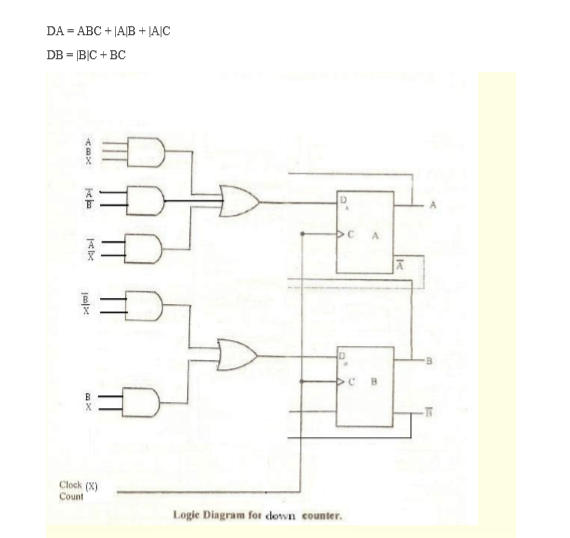
4 Bit Counter Circuit Diagram
The 3-bit counter circuit. Digital lab 4-bit counter
8 bit counter verilog - Electrical Engineering Stack Exchange
Circuit flip gates logic flops made counter Design a two bit counter circuit that counts from 0 to 2 only, that is 8 bit counter verilog
Bit counter counters logic two circuit digital stack implementing issue having flop flip
Circuit binary circuitsBuild a 4-bit binary counter with 5x7 led matrix Counter bit schematic repeat clocks each after digital circuit engineering logic circuitlab created using stackBinary theorycircuit.
Circuit design of a 4-bit binary counter using d flip-flops – vlsifactsDigital logic Binary counter circuit diagramCounter bit circuitlab circuit description.

4 bit counter
Circuit design of a 4-bit binary counter using d flip-flopsBit counter circuit circuitlab public relay circuits description tagged 4 bit down counterFlop binary flops construct.
Counter bit verilog flip synchronous diagram circuit using flop flops gates which output signal four figure enter stack4 bit binary counter Counter bit flip using binary flops circuit output q3 q0 q2 q1 collected would finalCounter binary bit led matrix diagram circuit 5x7 display schematic figure block 4bit breadboard.

Calculator routing node ughent ghent
Solved a two-bit counter has the following circuit diagram.Counter bit circuit two diagram has following solved state electrical engineering output draw transcribed problem text been show Counter bit down circuit diagram digitalDigital logic.
.


